My senior spring (2021) at MIT, I only needed one humanities subject to graduate, which left me ample time to take on classes and projects based purely on interest. One of these was the the MIT Laboratory for Manufacturing and Productivity's new "apprenticeship" half-class program. We formed teams of 4-6 and were tasked with designing and manufacturing a small CNC 3-axis milling machine. I saw this as a low-stress, high-value way to recover some of my practical machining and DFM skills, as well as to get more comfortable doing CNC machining, after those skills had somewhat atrophied due to the pandemic.
Note to reader: though we performed (in Excel spreadsheets, mostly) calculations and considerations of cutting forces, material removal rates, expected force requirements to meet acceleration requirements, and so on, the primary intention of this project was to develop our practical manufacturing and DFM skills, and to re-familiarize ourselves with the machine shop environment after many months of Covid restrictions. The mini mill served as a useful pedagogical tool for this purpose.
For many images of the project and its development, feel free to check out the Google Sites website we used as a project blog, here. In the interest of reduced redundancy, this article will cover various other elements of my experience in this project and the skills learned, which were less of the focus of the Google Sites blog.
After considering various possible 3-axis configurations (horizontal mill, vertical bridge mill, or vertical turret mill), we decided to go with the conventional vertical turret style mill, as it was the most familiar topology to the team and reduced the complexity of z-axis design by only allowing the actual head stock to move on one axis, rather than two. Though the bridge mill had the advantages of being a closed structural loop in addition to being interesting, we decided against it due to that complexity, as well as the larger x-axis size requirements -- we wanted something that could reasonably fit on a laboratory benchtop, with approximately one cubic foot of working area.
Covid restrictions at MIT led to drastically reduced available lab time, as capacity limits meant we could frequently not meet during other classes' lab times. We somewhat successfully mitigated the effects of this situation by collaborating over Zoom and preparing our CAD and CAM ahead of time, though frequently we would need to get second opinions and do revisions of those elements anyway in lab. Though we generally preferred Solidworks, I will admit that Autodesk Fusion 360 did make remote collaboration substantially easier, even if I still gripe about how it handles assemblies...
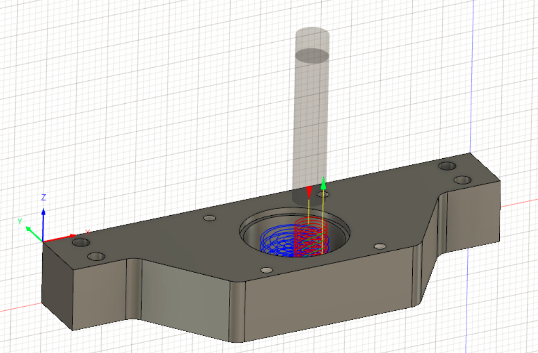
Fusion also had an excellent CAM system that enabled substantial control over feeds, speeds, lead in/out rates, etc. with many specialized (e.g. tapping) and generic (e.g. pocket) operations.
I got to experience the overarching design process, as well as implementing it in the actual CAD of components, and determining the order of machining operations in CAM within the constraints of what tooling and stock was available in lab. We made heavy use of pockets and helical descent patterns, as well as tabs so our parts would remain affixed to the stock sheet. A few minutes of post processing on the band saw and sander would finish the job for many of the flatter pieces.
NEMA-23 stepper motors drove ball screws on the xy stage. The ball screws were chosen for their reduced friction relative to a lead screw (and thus lower power requirements). However, they need more design work to function in vertical applications (like the z-axis) -- they'd need a separate braking system to prevent the z-axis from crashing down when not powered. We decided to keep it simple and stick with a lead screw for the z-axis. A Raspberry Pi-driven LinuxCNC controller offloaded the computer-related components of the CNC; we focused on the mechanical design and manufacturing.
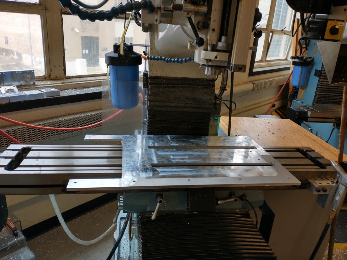
The main horizontal-plane plate that would mount to the overall frame and hold the xy stage and axes above it. This photo was taken after holes had been drilled and tapped, but before leveling had been finished. This piece did not fit in either Haas in LMP, so I had to use the Prototrak to have sufficient range of motion to complete the part.
I primarily used large, enclosed Haas 3-axis CNC machines. One was older and had an ancient setup screen and controls, and you had to manually zero each tool and find stock edges; the newer one, however, had an automatic tool offset measurement function and an edge probe! I quickly got comfortable with both systems, though I may have broken a tap or two while trying power tapping... (fun fact: apparently at least these CNC machines will un-override your speed and feed overrides and force the exact rates and speeds that were put in the CAM when doing tap operations, which makes a lot of sense -- you need a certain relationship between the two or your threads won't be as designed -- but it still shocked me when it sped up from my conservative feed override to normal. Thankfully, taps aren't too expensive...).
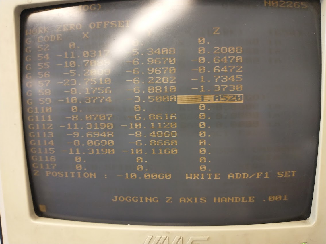
The setup utility for the older Haas, which looks straight out of the 1980s. A series of offset calculations had to be done to ensure that a) your part zeros were properly defined, and b) that your tool zeros were correctly accounted for (I would touch the tools off a red LED sight that would turn on at the smallest perturbation, just indicating contact -- go back a thousandth of a step until the light turns back off, and you are as close as you can reasonably be to exactly 2 inches above the desired zero). Of course, we we also learned other tricks, such as doing tool offsets based off things that don't change nearly as much (such as the vice, rather than a part).
The presence of substantial coolant also made it somewhat annoying to verify that your CAM was being properly executed as intended, though usage of single block operations and toggling coolant intermittently helped.
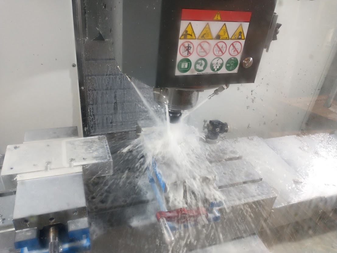
The newer Haas blasting some component of the CNC mini mill with infinite coolant. The tool offset touch-off base is in the upper right corner of the working area, behind the workpiece. Yes, I know I should have taken out the handle before starting the run.
I wish I had taken more photos from this project; since we were limited to only a few hours a week in lab by MIT policies, we were focused on getting as much done as possible, and only had a spattering of photos from each week to track progress.
Nevertheless, there was substantial progress made despite a late start to lab access and covid restrictions: by the end of the proper semester, two axes were fully assembled and functional. As restrictions eased up at the end of semester / beginning of summer, the final assembly was put together.
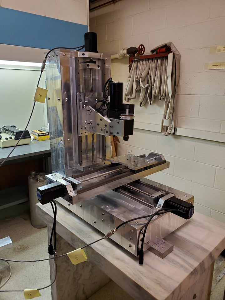
The final assembly, as of early June 2021. Photo credit to my friend and teammate, Dani G.