I don't like giving up on technological objects when they first break; I instinctively try to figure out a way to fix them. This has paid off numerous times: people have thrown away air conditioners that are perfectly functional, save for the fact that they tripped the GFI once; and I have taken thrown-out alarm clocks that couldn't produce alarm sounds, and opened them up to see what was wrong, only to discover that one of the solder joints leading to the speaker had been broken! A quick re-soldering and reassembly later, it was as good as new!
A similar fate I suspected awaited me with the case of my Baofeng CH-5 charging base. This is the port into which you plug a Baofeng UV-5R handheld transceiver, which operates on both 70 cm and 2 m, as well as being able to listen to common broadfast FM stations.
After hanging out with the MIT Radio Society for Field Day in June 2021, I discovered that the charging base had become damaged in transit in my backpack. The barrel jack connection was incredibly wobbly, and no power was going to the battery.
The first thing to do was to separate the base and reveal the PCB beneath, which was a lot more tedious than one might expect; though the bottom of the (all injection-molded, of course) base had a small impression where clearly similar parts used screws to assemble charger bases, this was instead a partial snap fit -- wonderfully simple to assemble, but a bit of a pain to pry apart. Thankfully, I was able to wedge several iFixit flathead bits in the non-snap-fit sections and, after inserting no less than four flathead bits in, I was able to pop out the snap fit -- with minimal destruction, too!
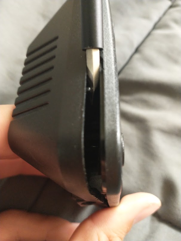
Though the picture does not show it well, I could see reasonably well within the hollow CH-5 interior and spot the problem -- a break in the charger's PCB!
The brains of the CH-5 charger are shown below:
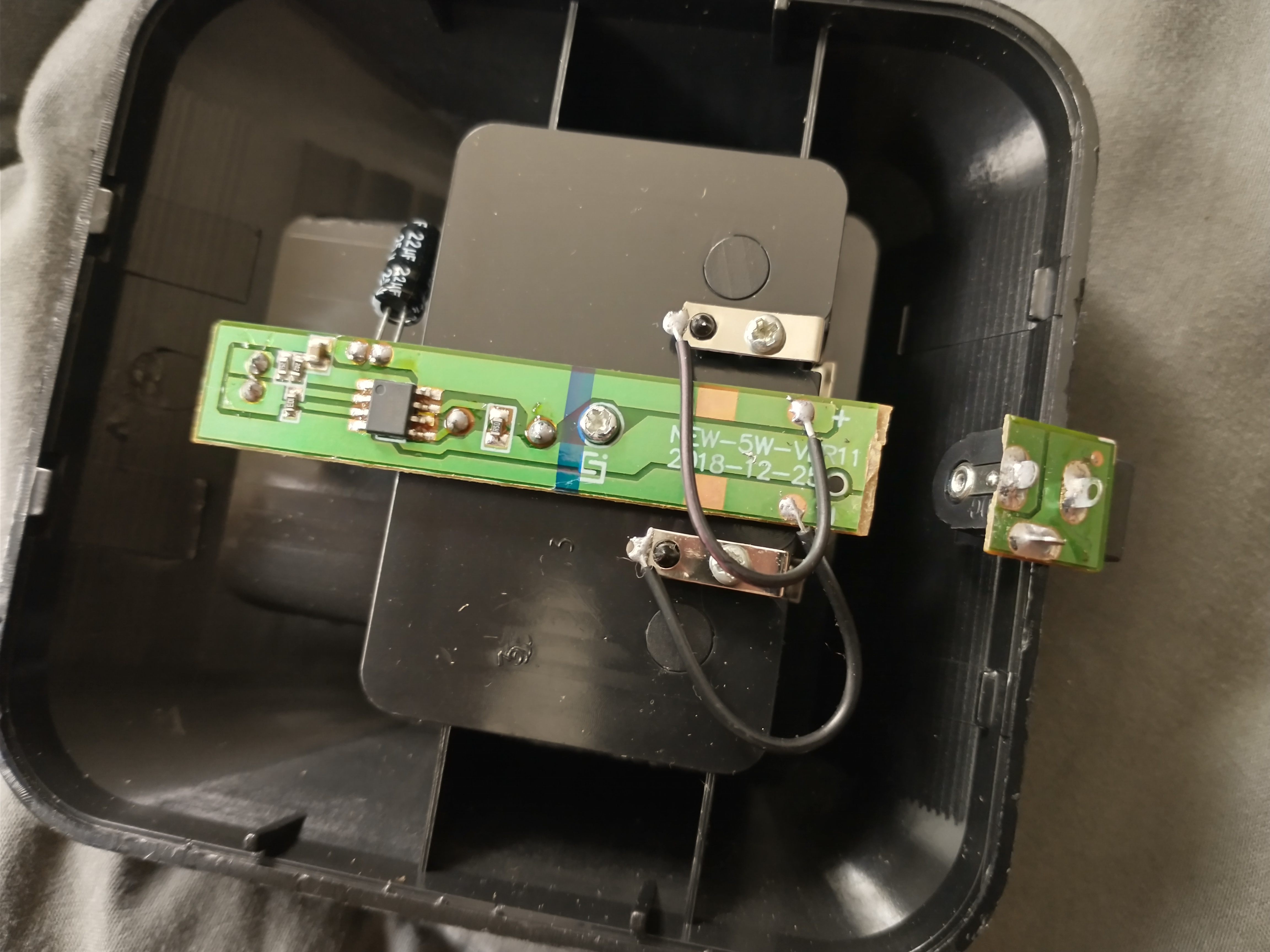
Can you spot the problem?
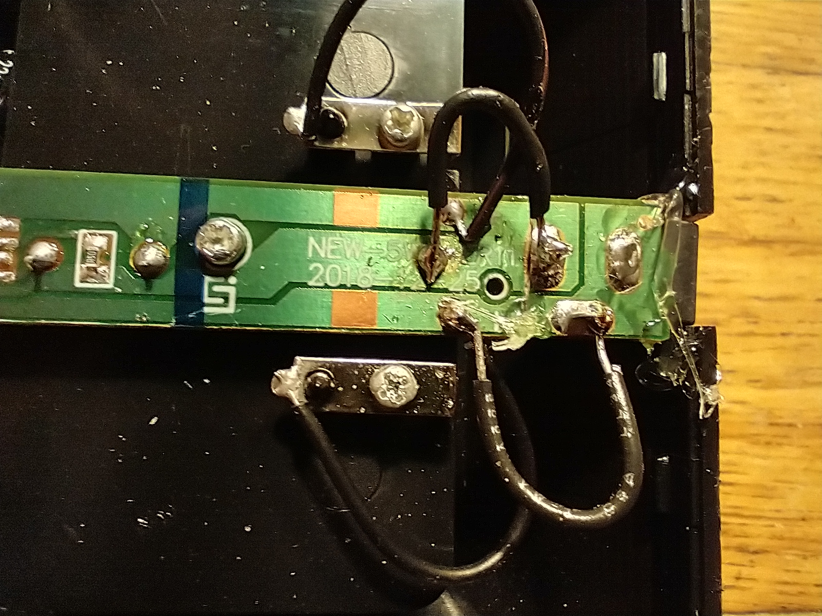
This is what it should have looked like (well, sort of):
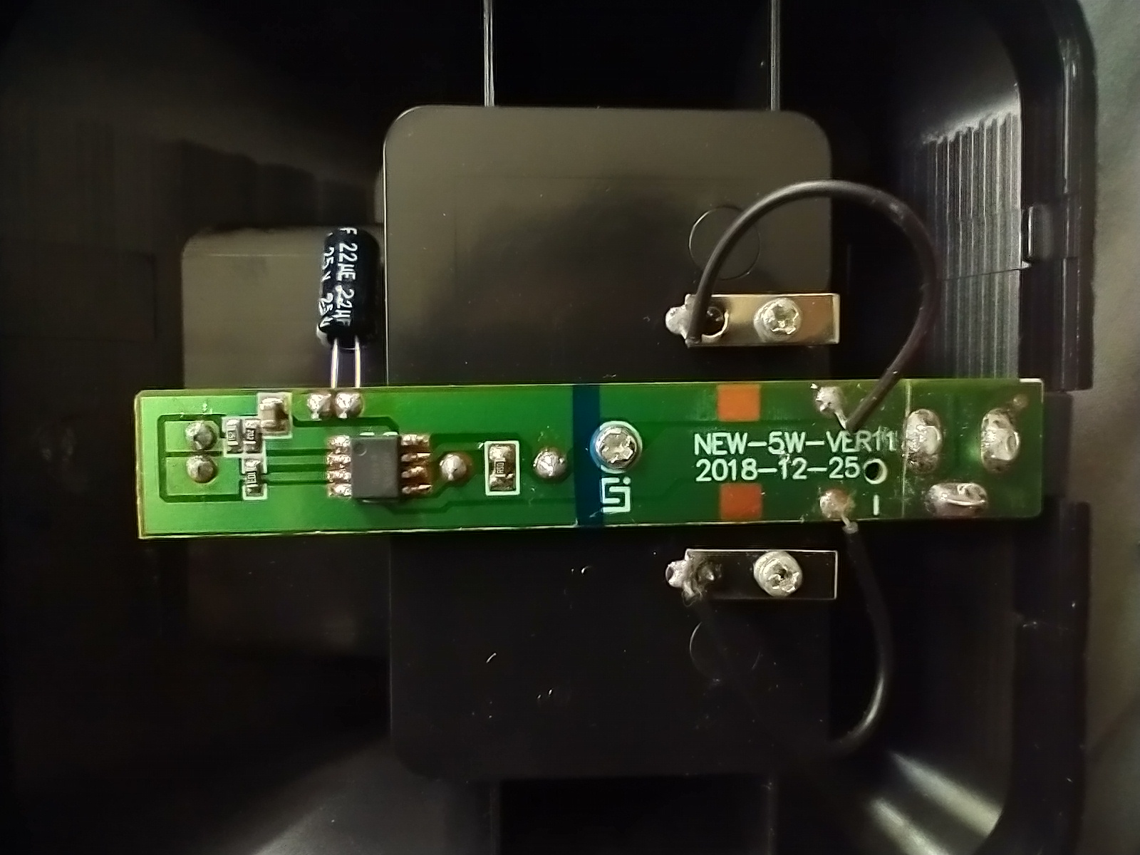
Sadly, repairing a PCB isn't as easy as just shoving the broken part back onto the rest of the PCB.
A bit of probing with my trusty Fluke multimeter and I was able to see what was going on. The dark green marks divisions between light green conductive regions (though I'd need to scrape up the light green coating to actually reveal the connection). One was clearly ground, and that left the high side for the other one. I presume the two electrically connected attachments for the barrel jack are for the supply ground and the shield, like in a USB connector (which I saw at and had to wrangle with in my time at Eli Lilly). The upper conductor in the above image, which goes to the positive side of the battery and is a stepped down voltage from the supply voltage of 10 V (at a maximum of 0.5 A) from a wall wart.
I'll also note that the edition of this charger PCB is "NEW-5W-VER11" with a date of 2018-12-25; I find this mildly amusing given that I technically bought the Baofeng UV-5R MK2, the "2020" edition. Clearly not much has changed in the charger (not that there is much to change, of course).
I initially had assumed that there was some op amp or linear regulator action happening in the SOP8 8-pin component to control the stepdown; I had to look closer at what the component was to do a lookup.
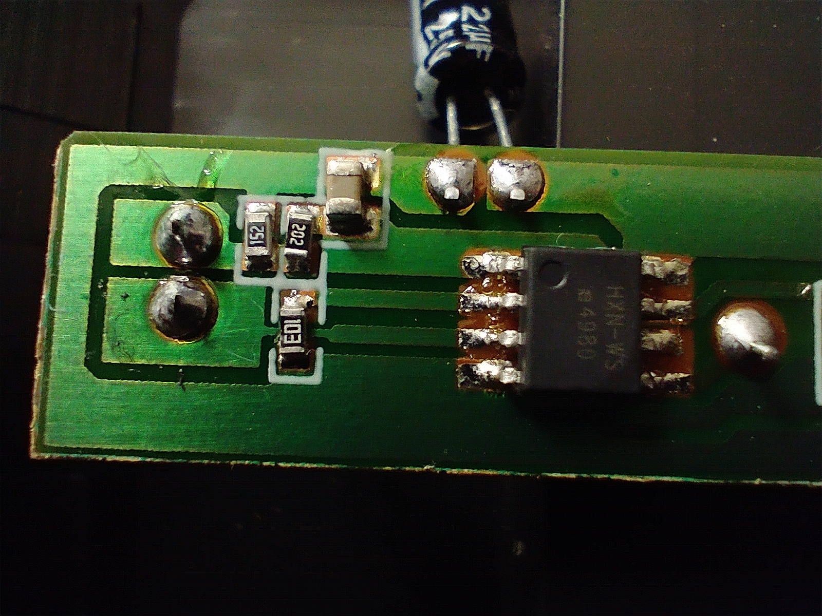
A closer view of resistors and capacitors and that SOP8.
The marking on that IC is: "HXN-WS e4980"; I looked that up, and presto -- Aliexpress tells me it's a linear CCCV charge management chip! Well, that's not surprising.
I also take an approving notice of the bypass capacitors to ground from high side lines near the SOP8.
The two solder joints on the far left there are the bottom end of the status LED that lights up the charger when power is applied.
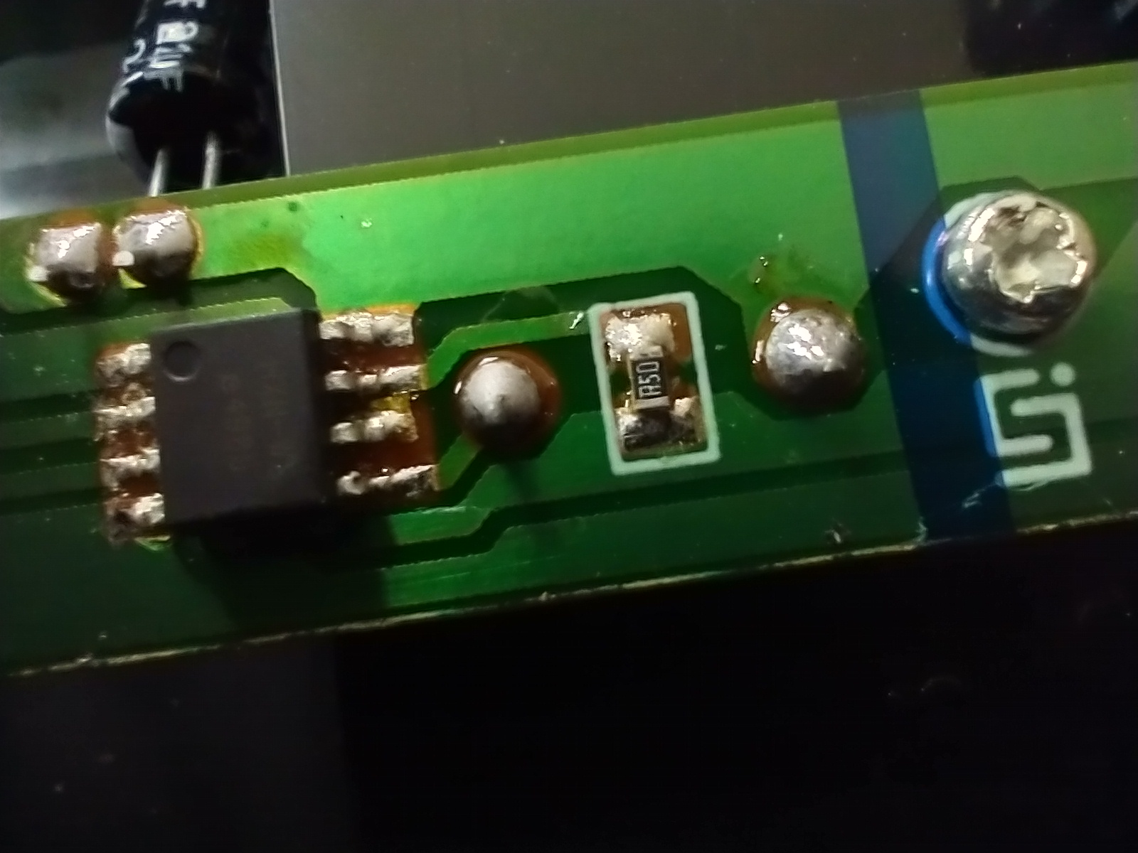
A view of the middle of that board up close as well, with the resistor shown.
In order to complete the repair of the charger, I used an Exacto knife to painstakingly yet carefully scrape up some of the light green on the hot side of the 10 V trace in order to solder a connection; the ground side did not need such a connection, as there was a handy solder blob on the unbroken side that I could simply attach a jumper to. A little hot glue later, and it was ready to be put back together!
I cleaned it up a little more after this shot was taken, but forgot to take another picture before reassembling. Not the prettiest interior, but better than ending up in the scrapyard.
I redid the snap fit and sure enough, the barrel jack once again snugly fit into the charger base!
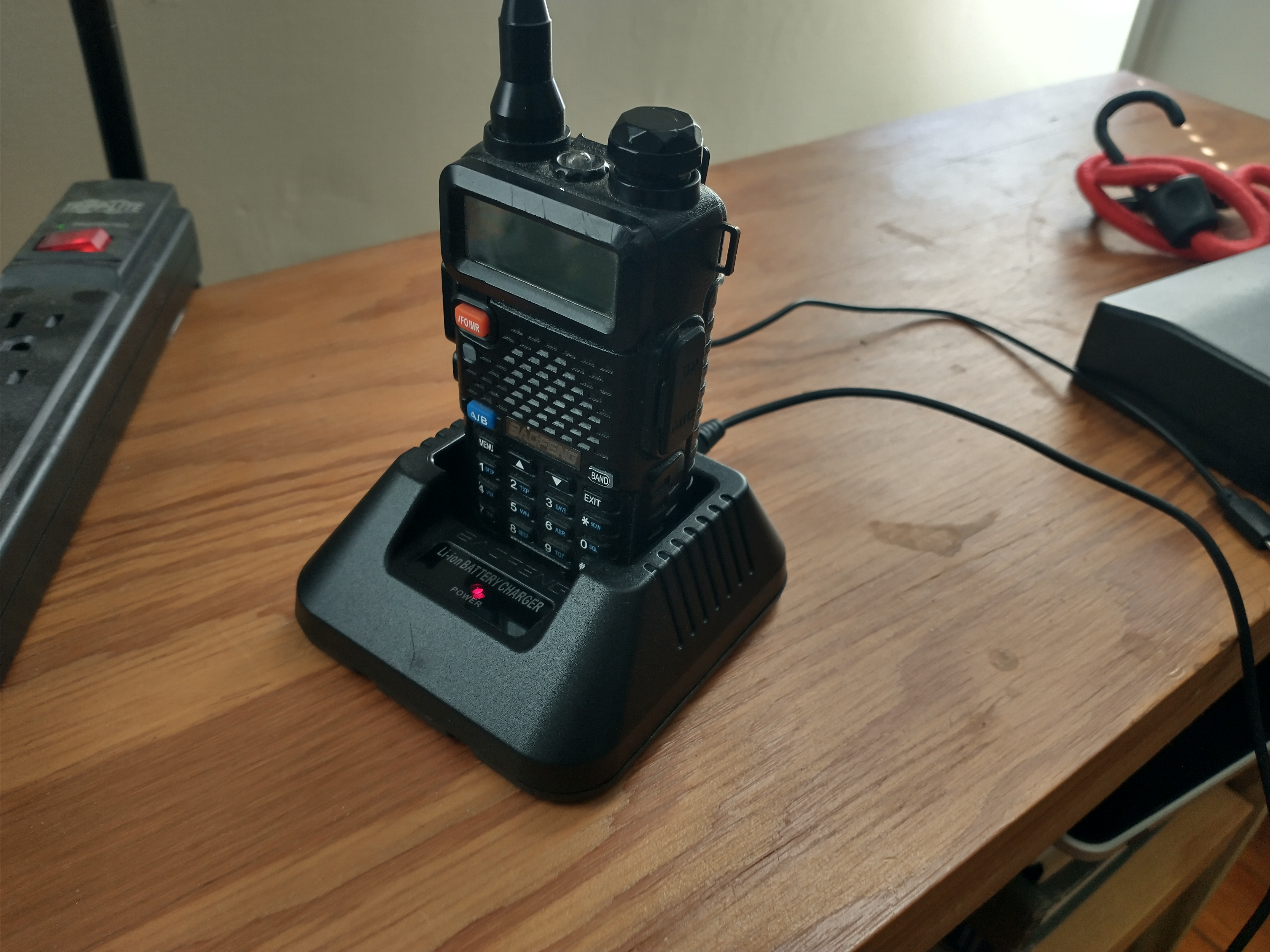
Just like new!