30. June 2023
My Startup Journey with Mytide Therapeutics
My first job out of undergrad was at a now-defunct company called Mytide Therapeutics. The premise was to have an automated system of manufacturing a class of pharmaceuticals known as peptides. There are many stages involved in the production of a peptide – from synthesis to cleavage, lyophilization to weighing, LCMS analysis to purification of product. The goal was to fully automate this to the point that all an operator would need to do would be to load fresh vials and top off reagents periodically on the input, and remove trays of complete, weighed, analyzed, lyophilized custom peptides for labeling, packaging, and shipment to customers.
My role for the first half year or so was primarily engineering support for the Gen1 peptide system, which was comprised of two separated workcells and various manual chemist interventions. I spent a lot of time troubleshooting error states and failure modes with the chemistry team, and would take my learnings back to the office to try to devise means of preventing the problems from returning (or if they did return, mitigating their consequences).
For instance: I noticed that we had a certain type of pump for moving the nasty chemicals (dimethylformamide, piperidine, etc) throughout the system whose failure mode when the sealing material degraded was to leak out the side. Since the stepper motors driving these pumps were directly underneath the pumps, that frequently led to completely unnecessarily destroying the motor alongside with the pump when these leaks happened. I designed, tested (off system first, then on system) and integrated a leak catch diverter system that a) provided an initial vessel to hold the leak fluid, and b) allow an Idex fitting to be inserted into the side of the catch chamber, safely draining it into the waste carboy for the system.
Other tasks in that first segment of my time at Mytide included the shadowing of the lab team and finding places where either unsafe or highly repetitive tasks could be mechanically amplified.
Blade Comb
One of these resulted in what I call the Blade Comb.
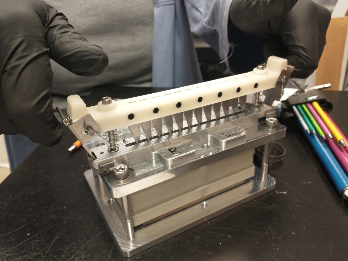
This might look somewhat concerning, but it was actually quite safe (if I were to make any change to it, it would be to add a clear barrier mounted to the metal portion on either side to make it even harder to hurt yourself with).
This device allowed one to create a controlled incision size in a membrane for 96-well SBS format lyophilization trays, one row at a time in a single stroke. The prior standard operating procedure for preparing a tray and its membrane was to take a needle and poke five holes in every single one of the 96 wells. Talk about carpal tunnel!
Tests were performed with vials in similar lyophilization trays at various incision sizes to recreate the same mass flow characteristics in the lyo as we had with the five hole pokes.
The Blade Comb was compact, functional, and designed for safety: the blades would only engage when you pinched both sides of the sheet metal catches on top to enable plunging. The 3D-printed (SLA) piece held springs and shoulder bolts to guide the travel, and to prevent binding, the sliding surface on the 3D printed piece was made to be a narrow flexure. The result was a smooth motion with controlled forces due to carefully chosen springs for maximal ergonomics. Once you let go (intentionally or unintentionally), the blades would immediately retract into a safe state.
Filter Press
Another problem I witnessed helping out in the lab at Mytide was that some of the peptides needed to be pushed through narrow filters in a few processing stages. Some peptides were fine, but others required unsafe levels of force, especially when combined with the fact that there was no fixture at all for doing so. I feared for the chemists’ fingers!
Eventually I was able to design and deploy a sheet metal-based system using an air cylinder and a manual valve to support filtration activities. I designed 3D-printed vial holders that you could push back into a vee-shaped catch that would concentrically align the vial with the air cylinder. I also designed the mating features to mount the air cylinder to the sheet metal framing and to mount the filter and syringe to the air cylinder.
I threw in a blast shield (in the event of vial product explosion, misalignment, etc, though I never witnessed it in practice) and blockaded the ability to lower the piston when the door was not in an open state.
Unfortunately I don’t seem to have much in the way of media currently of the filter press, when I find a photo or video (I know they exist) I will upload here.
Gen2 - a foray into system engineering and integration
Eventually as we fleshed out the engineering team, my role pivoted into being a kind of Gen1 guide for the larger engineering effort of creating a Gen2. Gen2 was set to bring the two separate Gen1 workcells together in one enclosure, scale up production dramatically, and eliminate most if not all of the headaches associated with the Gen1 system.
I worked primarily on the robot end effectors, the heater system for the first-stage synthesizer, and the overall system engineering. I also worked on the scheme for the detection and automatic alignment of the trays that would hold the vials and get moved around the workcell.
All of the pain points of Gen1 I sought to stamp out in the design of Gen2, frequently issuing guidance for how different modules other engineers were working on might interact with each other and with the SCARA robots that were conducting the peptide orchestra. I consulted with the chemistry team frequently to determine their process requirements (what lead lengths mattered most in LCMS? how many columns do we really need at different temperatures? and so on). I also acted as the intermediary between the W2 engineering team and a mechanical design contractor working on the frame and electrical system layout, eventually advocating for full hire into the team.
There are far too many interesting things I worked on at Mytide to cram into a blogpost, so I will briefly talk about a few: the tube gripper, the tray gripper, and the overall system design.
Tube Gripper
The tube gripper was a fun slick mechanism that used torsion springs, press fits, a cam traveled path, and taught me about the danger of galling. It had two grip positions, one with small compliant fingers to delicately pluck a vial out of a tray of its friends and a more aggressive toothed grip to grab a rib on the side of some of the vials to force it into and out of certain workstations. It was driven by an air cylinder to achieve a relatively constant force on the target.
Here’s a fun video of an early partial prototype:
Once converted to metal and fully assembled, I took the final version of the tube gripper through a life test gripping and releasing the various types of vials one would expect to encounter in the system, and ultimately it made it to approximately 1.4 million actuations before severe fretting occurred. We only needed ~0.75 million actuations per year on average anyway – so one could replace it about every 15 months and still be well within the safe, non-fretting zone.
Tray Gripper
The tray gripper was the result of a desire to have a consistent grip on the trays regardless of minor deviations in robot or tray position, unlike in the Gen1 system. The Gen2 tray grip featured a quasi-kinematic grip with a bit of compliance thrown in: two vees and a conical face on each tray were met with three hemispheres on fingers on a kinematic tri-grip, as demonstrated in the following video:
The trays themselves also were designed to be injection molded (with prototyping modifications for 3D printing) and had features that would create a proper kinematic coupling of three vees on deck mounts and three 400-series stainless steel balls in the trays. The 400-series stainless were magnetically responsive enough to drive little bouncing magnets in the deck interface plates that would a) fly past a hall effect sensor, indicating proper tray placement to the system and b) once elevated, provide a bit of an additional preload force in addition to the weight of the tray and contents to further seat the trays in the correct positions!
System Layout
Laying out the entire system felt like being an urban planner. Or playing Tetris. Or trying to cram ten pounds of stuff into a five pound bag.
We never got to fully build it (the deck and table came in, the synthesizer was being actively built up, the robots were in, the end effector had been tested and was built up, and ever more parts were coming together when we ran out of money).
Here is a render of the full system that I helped architect from the founder: